Justin Sapun, justin.sapun.th@dartmouth.edu
Tuna Ozturk, tuna.ozturk.th@dartmouth.edu
The goal of this project was to design a remote control car using embedded systems programming in C. Although the initial product used an HTTP protocol for Adafruit's wireless dashboard, we switched to wireless transceivers to reduce response time to user input and create a separate controller that doesn't require an internet connection. A fair bit of electronics knowledge was required as well.
Hardware Components
Arduino Uno (ATmega328p)
Adafruit Airlift Shield (esp32)
2 transceivers (nrf24l01)
2 - 9V DC motors
Adafruit DC motor breakout (Toshiba tb6612)
Linear voltage regulator (lm7805)
2 - white LEDs
2 - 4 digit 7segment displays with Adafruit LED breakout (Heltec ht16k33)
2 - 0.22uF capacitors
0.1 uF capacitor
2 - 9V batteries wired in series
Introduction
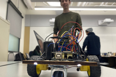
The car itself isn't the highlight of the project, but the remote operation of it. As such, the car was assembled from a rough compilation of laser cutouts. The steering was handled in software as the car had independent motors for the rear axles, thus, giving us the option to only use one front wheel and no steering rack. The batteries were wired in series to give more current to the motors and prevent the Atmega chip from browning out. We included 3 de-coupling capacitors across 9V and ground, the linear voltage regulator, and the TB6612 to protect the ICs from noise that may affect their performance. We used a linear voltage regulator to supply a steady voltage to the motors simultaneously. The TB6612 utilizes the H-bridge circuit enabling us bidirectional motor driving. Our first implementation utilizes the Adafruit Airlift shield to communicate via WiFi to the Adafruit Internet of Things Dashboard service. Our second implementation utilizes transceivers on the car and on a separate controller to communicate via the 2.4 GHz band. For fun, we included headlights (white LEDs) and taillights (SevenSeg Displays).
This project required us to study datasheets, create drivers, develop wireless communications protocols, and finally construct a driving operation. The project source code can be found on Github.
Implementation
We began by producing the necessary drivers for the following: tb6612, ht16k33, esp32, serial comm, and I2C comm. Building these drivers provided us with a standardized interface for software to access and control the hardware components while making the main code easily understandable. Note that to connect to Adafruit's Internet of Things, you need the network SSID and password, along with your own Adafruit account login. We used the Rest API over HTTP (the same protocol as regular web access). The framework consisted of HTML parsing for a single value from the Adafruit service.
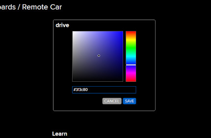
As our protocol only allowed for a single 32-bit value, we had to figure out a way to query a combination of two variables: speed and direction. During our initial design stage, we wanted to replicate a joystick to simulate the forward, reverse, and side-to-side motion. The closet controller we could find on Adafruit's dashboard was a color picker. We realized this would work with our protocol constraint, as we could export the color as a single value. Now in order to operate the car, the color would need to be set to “|||||||||” to zero the initial components of the blue and green hues. Once this is done on the dashboard, the color wheel will replicate a joystick and the two variables will be represented by the blue and green color components.
The video to the left is a quick demonstration of the car's functionality. As you can see we start by resetting the color wheel and then begin by increasing the car's speed in the forward direction. Ideally, the car should continue straight but that is not the case. We have concluded that because we used timer 1 and timer 2 onboard the atmega328p chip with different prescalers, the motors were not in sync when using PWM. As a result, we corrected this error in later developments by creating an offset. For the most part, the car still functioned as intended, able to operate remotely, turning left and right, or going in reverse. Note that we even included brake lights when the speed has been decreased. However, one thing we noticed right away was the 1 second delay from the Adafruit query.
To combat this issue, our next implementation was constructed using wireless communication on the 2.4GHz band using nrf24l01 transceivers. We built the driver in C and noticed the difference immediately. In addition, there was no single value constraint as we were able to send 8-bit arrays efficiently. Although we didn't have a joystick, this allowed the use of two potentiometers to signal speed and direction.
Skills
This project equipped me with the ability to create drivers for hardware components, program in embedded C, understand and implement basic electronics and circuitry, and develop comprehensive embedded systems. These skills empower me to create efficient and customized solutions for various applications in the field of embedded systems engineering.