Michael Dang, michael.dang.ug@dartmouth.edu
Justin Sapun, justin.sapun.th@dartmouth.edu
Mitchell Sylvia, @Amherst.edu
My main contribution to this project was a complete rewiring of the 12V low-voltage system to comply with safety standards. I also began the process of attaching components to the frame of the bike, namely the battery, controller, and charge port. I introduced a 3-speed function and variable regen with an LED display for its level.
Components
1996 Suzuki ZX6R Frame
Thunderstruck ME1507 (14.5 KW)
Kelly Controller KLS-8080N
500W Isolated 120V-12V DC-DC Converter
Domino Twist Throttle (5k)
30 LiFePO4 Prismatic Cells in series
ANT 32s BMS
Recent Updates - 08/01/2024
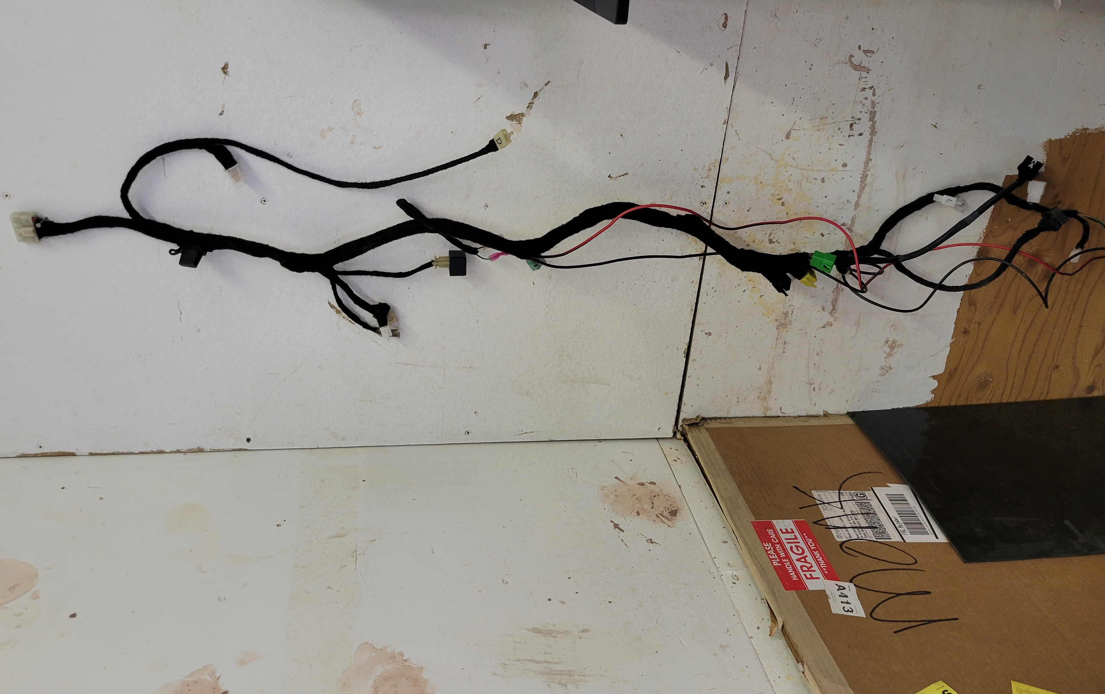
As of now, I am happy to say that I was able to successfully implement the 3-speed function and the variable regen. The 3-speed function gives the rider the ability to restrict motor power, and for good reason. The variable regen works by using a 5k potentiometer on the dashboard paired with an LED multimeter display to show the current voltage. This gives the rider a 0-5V reading of the current regen level, with 5V being the strongest. The regen only works when the engine start button is held down. This was planned from the start to give the user the ability to coast without holding the throttle, unlike many electric car manufacturers. The 12V wiring harness is complete!
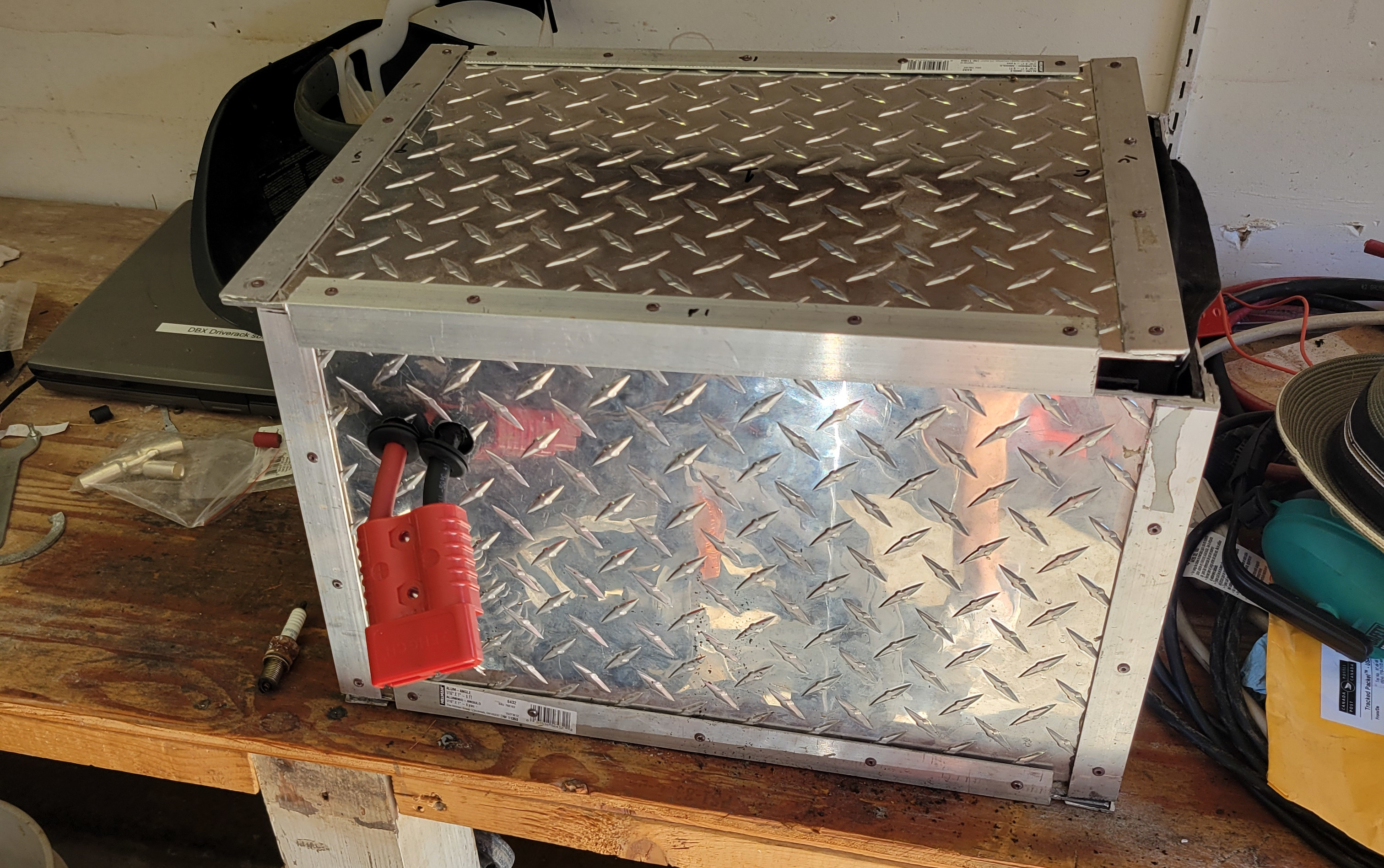
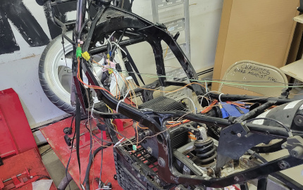
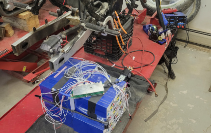
The bracket for the battery assembly was welded, primed, and painted to the frame of the chassis, finally making room for progress. The controller will be mounted to the bottom right of the battery, and the DCDC to the interior left frame rail. This allows for optimal weight balancing and current wire configurations. The charge port will be mounted to the original seat key lock in the left rear. We attempted to complete the battery by dropping it into the aluminum container with good isolation methods, but we deemed it unsafe due to an isolation error before ultimately taking everything apart. To the left is a photo of the assembled battery. More isolation proofing is needed. The next steps include further isolating the battery box, mounting drivetrain components, and creating a custom dashboard.
Update - 03/15/2024
We managed to get the motor calibrated using the cosine and sine hall sensors. This allowed us to get the motor to finally spin using the 5k throttle potentiometer. The weeks prior, we had difficulties with setting up and operating the BMS. The BMS is operational and includes unique designated charge and discharge buttons in the app. We have confirmed the battery accepts charge with limited current set to 10 amps. We have one main contactor for HV+ which works great with the old engine start stop button. The next steps in the process include manufacturing brackets for component assembly to the chassis and adding regen braking and the 3 speed feature.
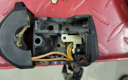
I will be adding a helpful feature to help adjust the regen strength while riding. This will be handled with a potentiometer and a multimeter display to help the rider know the current regen capability. On electric vehicles, regen is typically activated when the driver releases the accelerator or presses the mechanical brake. I thought it would be great for a motorcycle rider to be able to have the freedom to coast and choose when to activate regen. As a result, I chose to have the analog input routed through the start button switch from the right-handle bar control switches. I had to solder a separate wire to the start switch as it originally processed the same 12V input as the stop switch (which we need for other operations).
A complete redesign of the factory 12V wiring was required. The battery contained has been constructed and fitted into the bike. Brackets are currently being made to hold the box in place slightly above the motor. Other brackets will be made to hold other components to the frame or battery box. Currently, the BMS is not operational for the battery because we lost the temperature sensors. The Ant BMS believes the batteries to be too cold to use and will not allow discharging or charging. Once the BMS is operable, we will begin securing the battery into the box with appropriate isolation mechanisms.