Justin Sapun, justin.sapun.th@dartmouth.edu
With advancements in smart home technology, electric window shades have been introduced into the market. With a price point of around $90 on Amazon per window, extending this luxury to the whole house can be expensive. My solution proposes building custom automatic electric window shades with affordable components.
Hardware Components
-
2 Atmega328p microcontrollers, 16MHz crystal oscillator, 3 capacitors
-
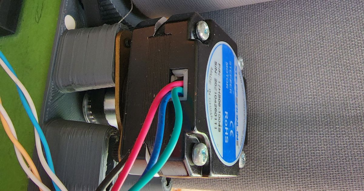
L293d H-bridge, ds3231 Real Time Clock, 5V worm gear motor, 2 nrf24l01 transceivers, tm1637 LED display
-
3V battery, buttons, switches, LEDS, 3V step-down regulator
Introduction
Like most luxurious things, they aren’t necessary. In this case, it’s still not necessary but I thought it would be fun to build and helpful when in use. The initial design of the automatic shades was a simple controller and receiver module. The transmitter would signal up or down movements of a worm gear motor which would drive the shades respectively. Difficult challenges arise when implementing automatic shade movement during sunrise and sunset time frames. The main challenge is detecting the current shade position and setting boundaries. As the design was rudimentary, there was no place for microswitches or sensors to detect these boundaries. Like most options on the current market, the transmitter will be a tiny remote with power reduction methods to save battery life. As the receiver module is stationary and could be plugged into a wall socket, there was no need to optimize power consumption.
Implementation
The transmitter device will be a wireless remote with 3 buttons, a 3-way switch, and 3 LEDS. The receiver device will be a stationary box that will also drive the motor. The receiver assembly consists of the receiver box, the curtain rod, and the other stabilization end. By turning the motor, the curtain rod will rotate and either spin the curtain up or down. Below is a link to the GitHub repository containing all the source code, and below are more implementation details.
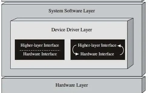
Drivers
One of the most important developmental steps in embedded projects is creating drivers for hardware components. Using drivers allows for high-level code in the main program and easy utilization of various components simultaneously. In this project, I built 3 drivers for the two-wire I2C communication for the atmega328p microcontroller, L293d h-bridge, ds3231 RTC, and modified 2 existing drivers for the nrf24l01 transceivers, and the tm1637 led display. See various driver and demo files here.
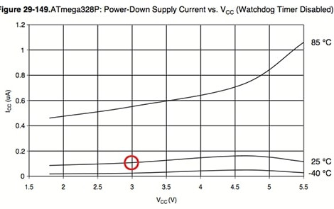
Power Consumption
As the transmitter would have to be a wireless remote, it would need a battery. As the nrf24l01 transceiver and atmega328p processor can handle 3.3V as an input, it seems a 3V lithium battery is ideal. If there was no consideration of power consumption, the barebones processor draws 15mA while the nrf24l01 draws 0.33mA when idle. For a standard 3V battery with 150mAh capacity, the device would operate for only 9.78 hours. This isn’t going to work. The atmega328p poses some sleep modes which could be set by changing register values, which I simplified in the powerDown driver. By additionally shutting off internal components in the microchip, like the analog-to-digital converter, I was ultimately able to reduce total power consumption to 17uA when not in use. The nrf24l01 chip can be shut down which can reduce its consumption to less than 1uA when not in use. Ultimately, a 3V lithium battery could theoretically result in a battery life of 347 days, almost 1 year!
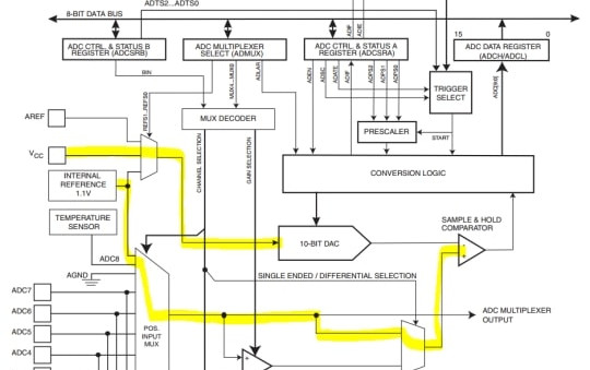
Battery Guage
I thought it would be helpful if the user was aware that the 3V battery was getting low. Instead of using an external voltage reader, using the atmega328p analog to digital converter, you can measure a known voltage (the internal 1.1V reference) using an unknown scale (the Vcc battery voltage). Unfortunately, with this method, you will need to calibrate every new chip and battery voltage.
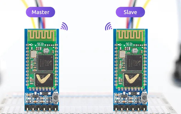
Connection Protocol
To ensure connection between the two devices, I created a brief connection protocol. When awakened by the power button, the transmitter would send a known message to the receiver. If the receiver is within distance, it will then repeat that message back to the transmitter. If the known message is the same as the received message, the device flashes a green LED. If the receiver is not within distance or the connection is not well established, the transmitter will keep flashing the green LED. If there is no viable connection in 10 seconds or no button is pressed, the transmitter will go back to sleep. To ensure the user is aware of the connection status, the devices continuously run the connection check every so often when the transmitter is awake.
Shade Position Detection
Instead of using physical limit switches, the receiver estimates shade position using a timer based counter. Every 0.1 seconds an "up" or "down" command is received from the remote, the system increments or decrements a counter to track shade movement. To enable this, a calibration mode lets users define the top and bottom bounds manually. A toggle switch on the receiver allows the user to switch between setting the "top" or "bottom" position. These bounds are then used to limit movement during automatic operation and prevent the shades from overextending in either direction.
Custom PCBs
I designed custom PCBs for both the remote and receiver to minimize wiring and fit everything into compact enclosures. Each board was tailored for its components and layout needs. The image to the left contains the transmitter design.
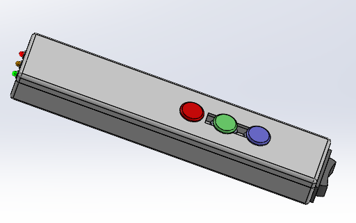
Custom Housing Enclosures
I designed custom 3D-printed housings for both the remote transmitter and receiver. Each enclosure was sized to fit the PCB and components snugly. The exploded view to the left is the receiver module.
Recent Developments
All code has been completed, tested, and verified using Arduino boards. PCBs for both the remote and receiver have been received, and the 3D-printed enclosures are finished. I’m currently assembling and programming the custom PCBs. Full testing will begin once assembly is complete.
Skills
This project strengthened my embedded programming skills in C++, including writing custom drivers for I2C, SPI, and motor control. I gained hands-on experience with bare-metal microcontrollers, power management, and RF communication. I also designed and tested custom PCBs, created 3D-printed enclosures, and integrated hardware and software into a complete wireless, low-power mechatronic system.