Justin Sapun,
justin.sapun.th@dartmouth.edu
Madeleine Carr, Madeleine.Carr.25@dartmouth.edu
Abby Hughes, abigail.hughes.25@dartmouth.edu
Thea Kunzle, Thea.E.Kunzle.25@dartmouth.edu
To improve the efficiency of air source heat pumps (ASHPs) in cold climates, our team explored integrating pulse electrothermal de-icing (PETD) technology as an alternative to traditional reverse cycle defrosting. We developed a series of electrical prototypes and tested them against the performance of a full ASHP under natural icing conditions.
Hardware & Test Components
- Mitsubishi Hyper Heat ASHP (AOUG09LZAH1)
- Eyedro Home Energy Monitor
- Impeller anemometers and thermistors
- Custom transformer + isolated variac
- Triac-based switching circuit with optocoupler
- Fluid loop using RV antifreeze
Introduction
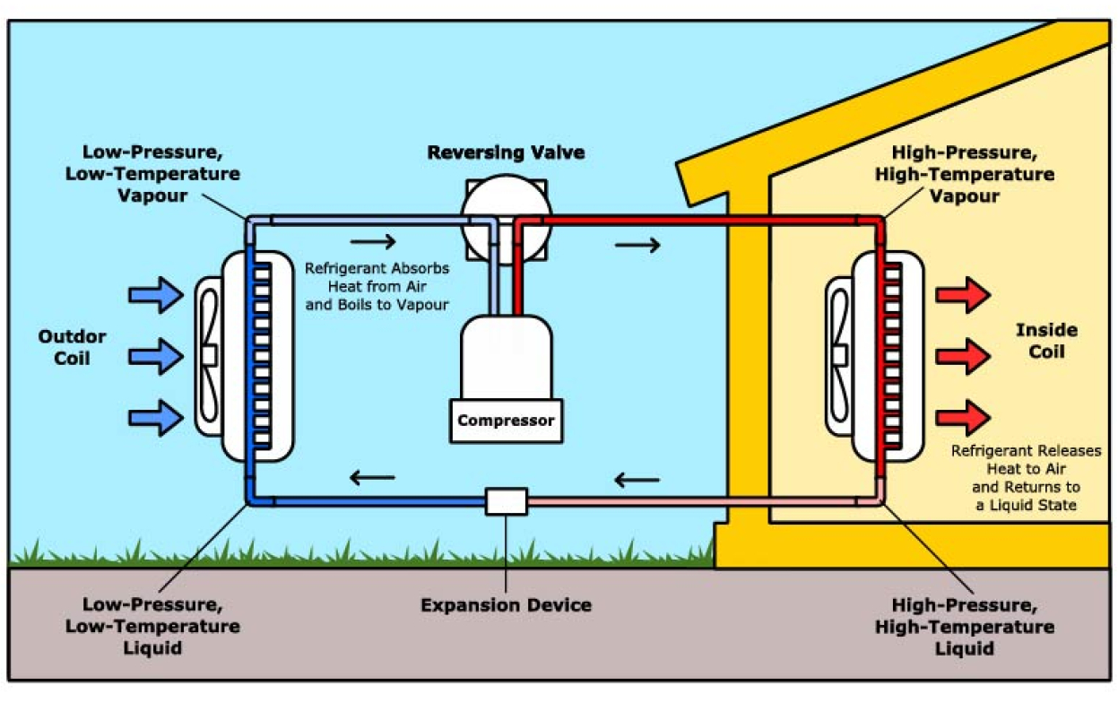
Air source heat pumps (ASHPs) are an increasingly popular option for residential heating due to their high efficiency and use of ambient air as a renewable energy source. However, in cold climates, frost and ice buildup on the outdoor unit severely degrades performance, forcing the system to periodically switch into reverse cycle defrost (RCD) mode. This interrupts heating, consumes energy, and stresses the mechanical system.
Our goal was to address this limitation using Pulse Electrothermal De-icing (PETD), a patented technology that removes ice via short bursts of high current. Unlike RCD, PETD aims to remove frost without reversing the system and interrupting heating. This project explores whether PETD can be effectively applied to ASHP condenser coils, a nontraditional surface for this technology. The full report and presentation can be found below.
What is PETD?
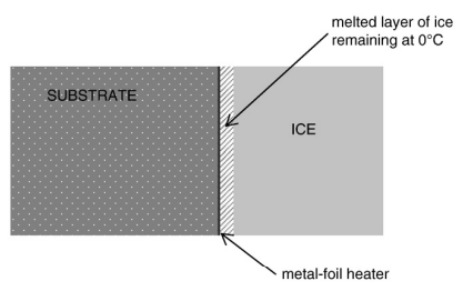
Pulse Electrothermal De-icing (PETD) is a patented technology that removes ice using short, high-power electrical pulses. These pulses generate intense localized heating at the interface between the ice and the surface, melting just enough to break the bond — allowing gravity to remove the ice.
Originally developed for smooth surfaces like airplane wings and power lines, PETD works by exploiting ice's electrostatic adhesion. This project explores a novel application of PETD on the complex surfaces of ASHP condenser coils, which introduces new electrical and thermal challenges.
This video demonstrates how PETD pulses break the adhesion layer between ice and the test surface. A thin water film forms almost instantly, allowing the ice to slide off with minimal energy. This principle guided our hardware prototype design.
Testing Approach
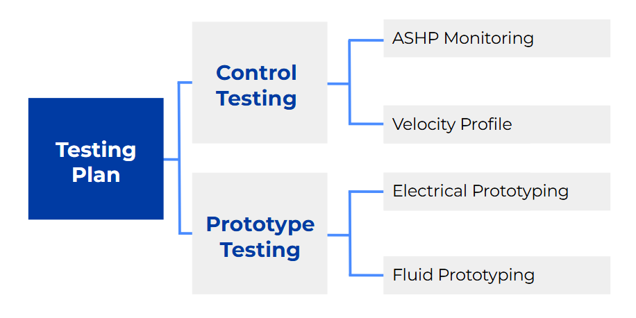
To evaluate PETD's viability as a deicing method for ASHPs, our team divided the work into two major tracks: Control Testing and Prototype Testing. This parallel design approach allowed us to analyze both the baseline performance of a standard ASHP system and the effectiveness of our PETD prototype under controlled and natural icing conditions.
The Control Testing team monitored ASHP behavior through thermistors and anemometers, measuring CoP, airflow, and power usage during standard, partial, and full defrost cycles. The Prototype Testing team focused on electrical safety, transformer performance, and de-icing behavior using various PETD coil prototypes in a simulated cold environment.
By comparing energy consumption, deicing times, and thermal behavior across both test tracks, we aimed to determine whether PETD can offer a meaningful efficiency advantage while maintaining system safety and reliability.
Control Testing
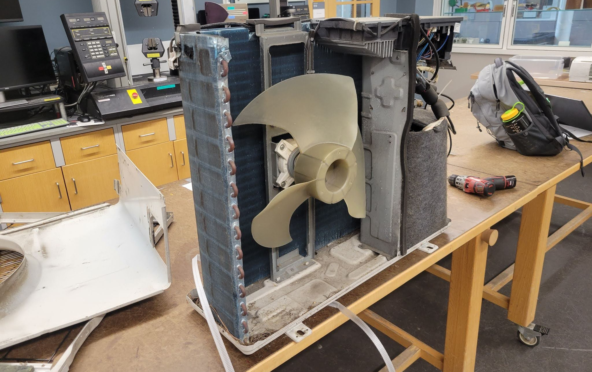
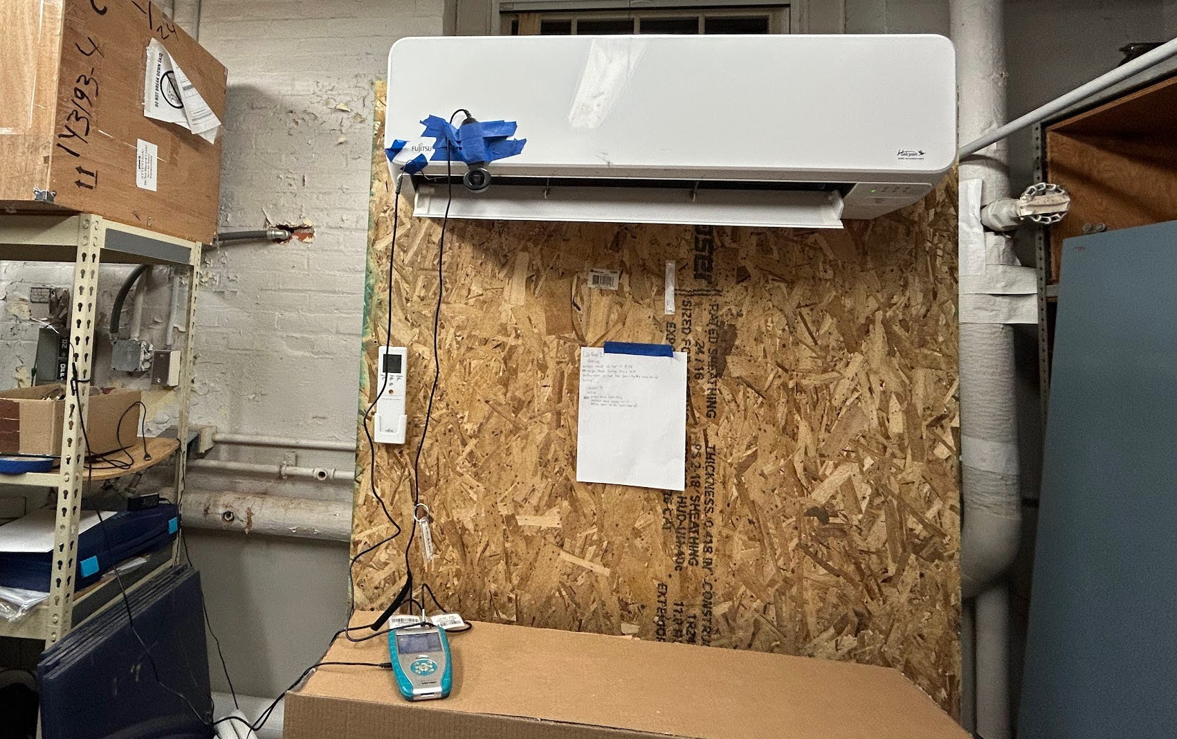
To understand the baseline performance of our ASHP system, we installed a Mitsubishi Hyper Heat indoor and outdoor unit and ran tests during real winter conditions. We tracked temperature, airflow velocity, and humidity at both the inlet and outlet using calibrated sensors. Power consumption was recorded using an Eyedro energy monitor.
Our goal was to capture the system's behavior during standard heating, partial defrost, and full defrost cycles to assess energy consumption, CoP, and how quickly the system could respond to varying thermal loads.
Prototype Testing
While control testing focused on understanding ASHP baseline behavior, our prototype testing centered around evaluating PETD’s ability to deliver high-power pulses safely and effectively to a finned copper coil under icy conditions. We progressed through three major design stages, each intended to improve power delivery, reduce parasitic resistance, and ensure safe handling of high current.
Soldered Wires
Our first prototype consisted of a single copper tube mounted in a 3D printed stand, with six 12 AWG wires soldered directly to the tube. Although functional, the design suffered from high parasitic resistance in the wires and mechanical strain at the solder joints, limiting power efficiency and raising thermal concerns during operation.
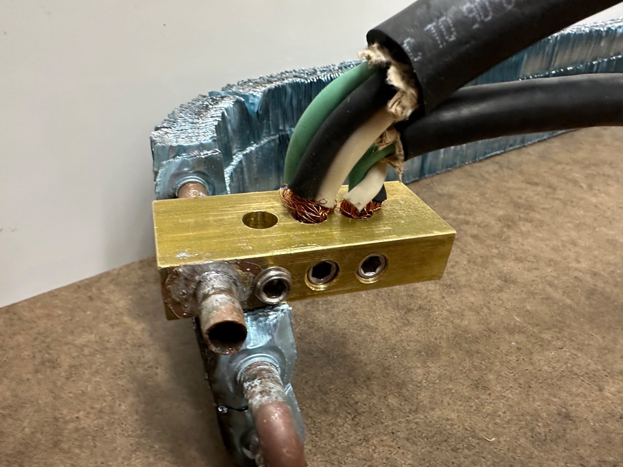
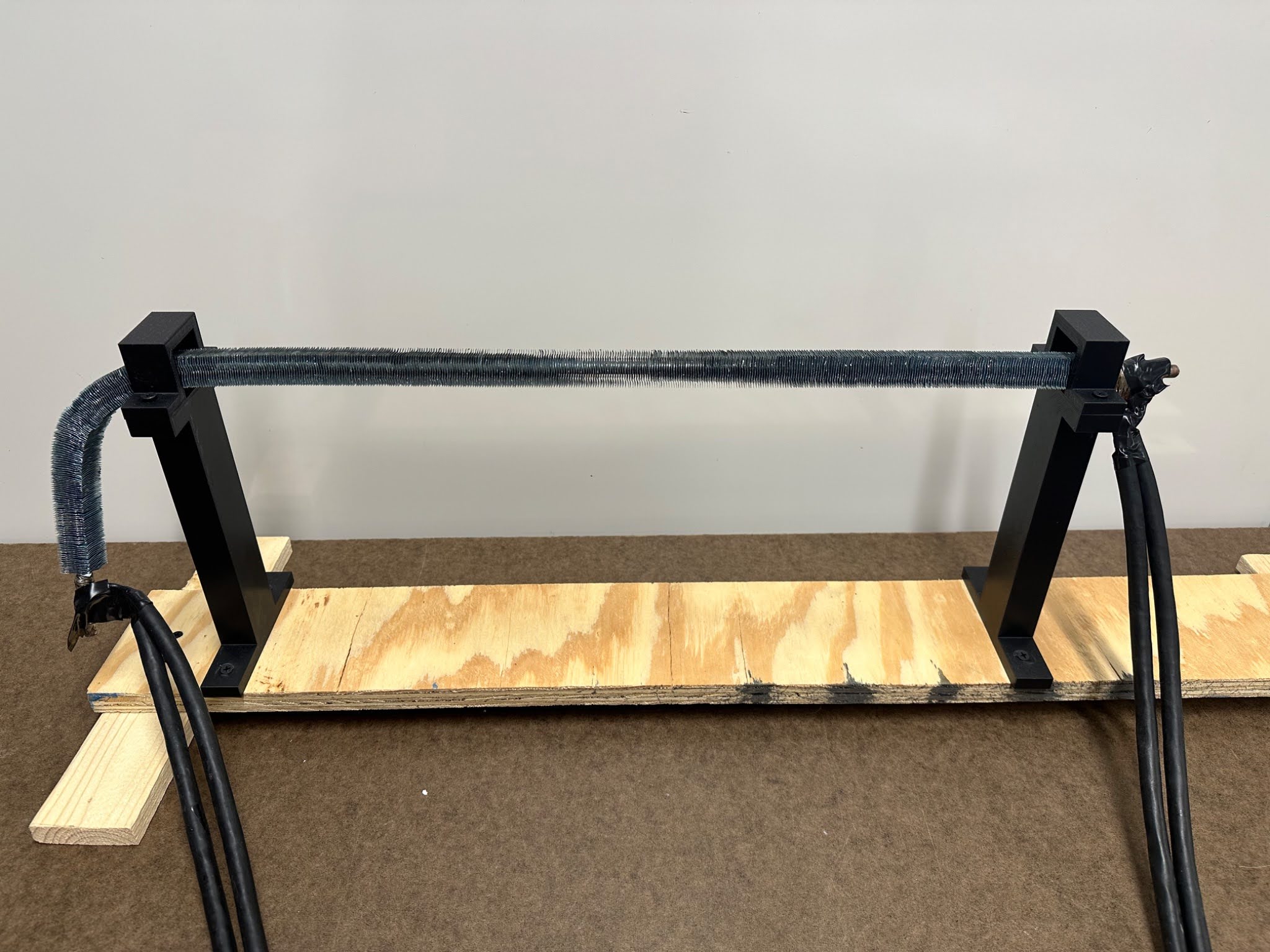
Brass Bus Bars
To address these limitations, we moved to a 3-length coil design with custom-fabricated brass bus bars. These bars significantly reduced interface resistance and allowed us to clamp multiple conductors securely. Although brass is less conductive than copper, its availability and mechanical strength made it an effective intermediate solution for distributing current more evenly across a longer coil.
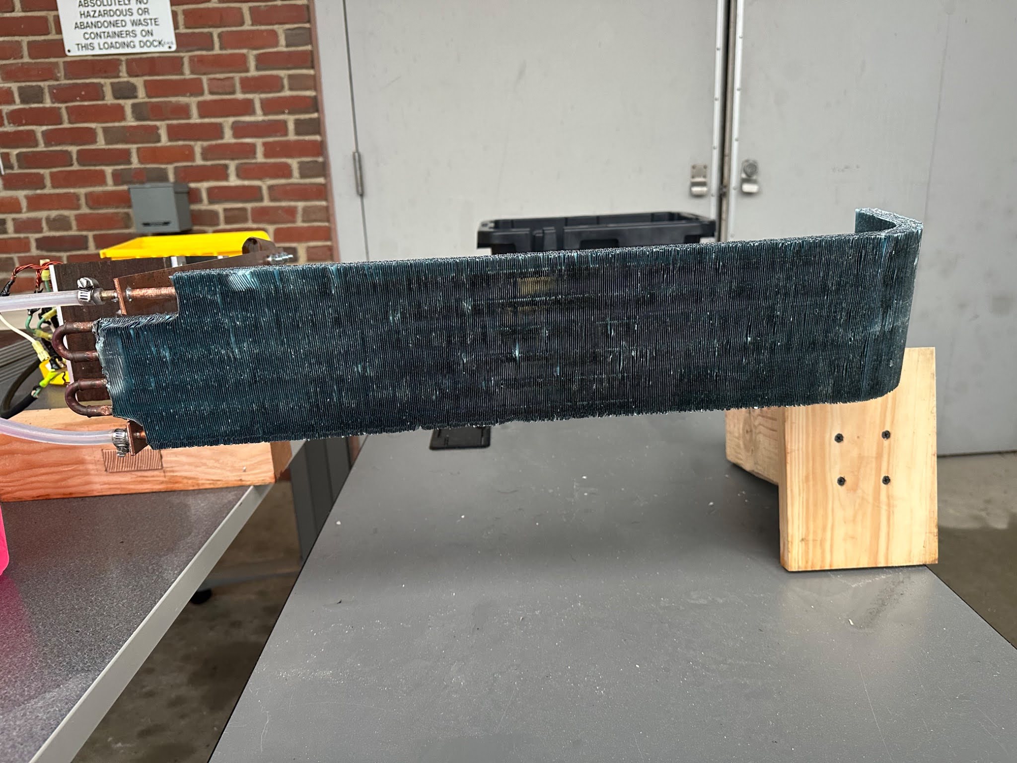
Copper Bus Bars
Finally, we developed a 6-length prototype using high-purity copper bus bars. These were soldered and mechanically fastened directly to the transformer secondary terminals and the full-length coil. This design offered the lowest resistive losses, greatest thermal uniformity, and best alignment with PETD's theory of short, high-power pulses. It also brought us closest to the real-world conditions of a full ASHP coil system. The header image shows the bus bar connection.
Driving these prototypes required delivering pulses of 110-120V AC at peak currents upwards of 15A. To accomplish this safely, we designed a custom power supply unit (PSU) capable of switching AC pulses via a zero-cross triac circuit. The switching was controlled using an opto-isolated MOC3062, which allowed us to decouple the microcontroller logic (5V) from the AC load line. This ensured safety while allowing precise pulse timing control.
Our original design used an ATmega328P for pulse control, paired with a logic-controlled gate for the triac trigger. We laid out and tested a dedicated PCB for the system, including heat dissipation considerations and snubber protection. Our PCB design followed IPC clearance and creepage guidelines for 240 AC mains. For field testing, however, we opted to use a commercial variac and an off-the-shelf triac control module to reduce the risk of catastrophic failure and to expedite testing outdoors. Below is the 3D model of our power supply with a custom PCB.
Results
We tested three PETD coil configurations: 1, 3, and 6 lengths to evaluate heating response and energy efficiency. The 6 length prototype performed best, deicing in just 2 minutes and 28 seconds with a total energy input of 283 Wh. In contrast, the 3 length design required 4:54 minutes and consumed 535 Wh, while the 1 length version took 6 minutes and used 363 Wh.
Extrapolating these results to full condenser coil operation, we estimated an average PETD defrost cycle to consume around 0.432 kWh. Under favorable conditions, this could drop to 0.342 kWh, while in heavier icing scenarios, energy use may rise to 0.613 kWh per cycle.
Compared to reverse cycle defrost (RCD), which used 0.702 kWh per cycle in our monitored ASHP system, PETD offered up to a 39% reduction in energy. Additionally, PETD avoids the heating interruption that occurs during RCD, offering a more seamless and efficient defrost strategy.
Due to many potential variables that could have influenced our experimental results such as inconsistent weather, uneven ice formation, and sensor variability, our project did not provide entirely conclusive results. However, the data we collected strongly supports further investigation. With more controlled testing, PETD could prove to be a highly effective and scalable defrost solution. If validated, this technology has the potential to reduce energy usage globally in heat pump systems.
Skills
This project strengthened our abilities in high-power circuit design and embedded C programming for real-time control. We developed and tested triac-based power switching circuits, characterized custom transformers, and designed multiple PETD prototypes for high-current applications. Additional skills included PCB design, 3D modeling and fabrication for coil fixtures, microcontroller integration, and detailed performance modeling based on heat transfer and icing theory. We also implemented HVAC monitoring instrumentation and performed CoP calculations to compare PETD and reverse-cycle performance.